What is a Driver?
A Driver is the template that holds pertinent information about a device for Accelerator to communicate with. Drivers include everything from basic information to detailed information as to what function of the device Most of the heavy lifting generally associated with creating macros, devices, layouts, etc., is Automated flawlessly with a properly created driver. This allows the programmer to spend time creating custom or special macros.
Some Basic information that can be found in a Driver includes (but is not limited to):
Edit Information:
- Brand: the brand of the device being used
- Models: Model number/s of the device used to identify it from the library
- Device Type Category: the category of the device used to organize the different types of devices in the library
- Default Sub-Menu: When Accelerator automatically generates User Interfaces, this is the sub-menu the device will be placed in
- Control Types: (IR, RS-232, IP) the protocol used to communicate with the device. Relays and 12v Triggers can also be used to communicate with devices from specified base stations.
- Outputs: Lists the available outputs or zones of a device. Outputs can be audio/video or both (ie: matrix)
- 2-way (VFD): If there is an available two-way associated with the driver, the file location of the script is located in this field.
- Power Management & Macro Delay:
- Power On Delay: Amount of time the system pauses before sending another command to the device. (ie: a TV generally takes several seconds before the Input command can be sent. This delays the system before sending the command)
- Power Off Delay: Amount of time the system pauses after shutting down a device. (ie: projectors often require 30 or 60 seconds after shutting down before turning back on)
- Macro Interstep Delay: Amount of time between two commands. This helps to delineate each command so there are no confusion when being sent to the device.
- Analog/Digital input: Lists the available inputs on the device. Mandatory in the auto creation of macros.
- Built-In Sources: Many devices have built-in sources (often called Apps, Smart Hub, Tuner, etc.) Any built in sources created in the Driver are automatically generated as a source in the programming. Accelerator also creates an interface and macros for all built-in sources.
Edit Functions:
● Delays (Power ON/OFF & INTERSTEP)
These are the delays needed for various power states and general control.
1. A Power ON delay is the time that a device needs before it can accept any other command once
it is turned on.
2. A Power OFF delay is the time a device needs before another command is accepted AFTER it has
turned off.
3. The Interstep delay is the time that it takes, during normal operation, between commands issued
to the device. For example, issuing a favorite channel command like 247 would be automatically
executed as 2, interstep delay, 4, interstep delay, 7, interstep delay.
● Output zones
Although this category mostly applies to Audio-Video Receivers (AVRs) and Matrix Switchers, this informs
URC Accelerator of the device’s capabilities. It enables the device to play one of its sources
(internal source or external input) in other zones.
● External inputs
It is necessary to add the amount of external inputs available with their associated names into URC
Accelerator before automating macros.
● Internal sources
The driver populates with the names and control codes for each source to make the internal sources
accessible.
● Device Layouts
Each device has a default layout (the name/location of the soft buttons) associated with it, even
though it may still be changed within the project.
As you can see, a well-made driver increases efficiency, saves time and can be used repeatedly.
Do all devices need drivers?
It is recommended that each and every device within a project have an associated driver, but some devices
do not actually need one. Devices without internal sources, zones or inputs can use the traditional CCP
method of entry using the associated (IR, RS-232 or IP) navigator.
Devices that always need a driver and have one or more of the following:
● Output zones
Used if there is more than a single zone.
• Every AVR needs a driver to function correctly regardless of the number of zones.
● Internal Sources
Used if the device has more than one internal source that has discrete codes and source selection.
• If a device has internal sources that are only accessible through a MENU based system, then
a driver does not need to be created (e.g. using the DVD menu to navigate to Netflix; this method
does not need a driver).
● External Inputs
Used if other devices can be connected to it.
• This needs to be created so that URC Accelerator can create macros to automatically take care of
all of the switching necessary to perform the desired activity.
Good examples of these types of devices:
● Audio Video Receiver
These typically have all three qualifications: with internal sources (AM, FM) and multiple zones with
external inputs (Cable, TV, AUX). These devices always need a driver.
● Display Devices
Although these do not normally have zones, there are usually a few external inputs and in the latest
displays, even internal sources (YouTube, Netflix, etc.) that need to be declared.
● Matrix Switchers
By their definition, these always need a driver as they have external inputs that feed zones.
Devices that do not need a driver but could only benefit by having one:
Cable Boxes
Most cable boxes do not have an input. They only have a single internal source (cable) and only feed a single
area/zone. If none of the preceding is true, then a driver must be created for this device (e.g., built-in
Netflix (TIVO) or Dual Outputs (DISH).
DVD Players
Although this device may NOT need a driver if it has no internal sources, most of these are now available
with internet sources (Pandora, Netflix, Hulu, etc.). They could require a driver to be created, if those
sources have discrete access and commands.
Remember, using this method (without a driver) means determining a layout, checking timings and renaming
the device for each project where the device is used. Creating/using a driver saves time by allowing all
of these to be created a single time, and then reused when necessary.
My Database Ribbon Menu
The My Database portion of URC Accelerator was designed to help you create, edit and manage the devices
within My Database.
My Database works in conjunction with the standard URC database by keeping the most commonly used and
user-created drivers within its easier to navigate database. Not only does My Database contain all user-created
or edited drivers, it can also be used to save any current driver. This smaller subset of the entire URC database
allows for easier navigation and quicker discovery of the devices within your project.
URC recommends saving devices to this section if they will be used on multiple jobs. The three sections found
within this ribbon are:

New Driver: This selection allows you to create a driver. This driver can be created from scratch, based
upon another driver or codeset within the URC database.
Edit Driver: This selection allows you to view and/or edit a pre-existing driver found within the URC
Database or My Database. This is the only way to create a new driver based upon a user-created
driver.
MRX-20 Favorite Channels: Disregard this for now as it is unrelated to driver creation.
Manage Database: This selection allows the user to view all of the drivers within My Database and
delete, rename or copy them.
New Driver
Selecting this option opens the Create A New Driver window. When a new driver is being created, the initial
decision is to determine whether to create this driver using an existing driver as a template, or to create one
from scratch. This window has three options (detailed at the bottom of the window):
Cancel Driver Creation: Selecting this option closes the window and returns you to URC Accelerator.
Start Blank - Device Not Found: Selecting this option allows you to begin the driver creation process
with a blank slate as you produce a driver from scratch. For more details on this process, see the
section Drivers: Starting From Scratch.
Select This Device: Select this option if you intend to create a new driver based upon an existing driver
(or codeset) within the URC database. For more details on this process, see the section Drivers: Using
Existing Devices.

Edit Driver
Selecting this option displays the Open file window. By default, this window opens to the default driver
location and populates all of the drivers in My Database (upon initial viewing, assuming no drivers were copied
to this folder, it will not contain any files).
Choosing an existing driver or generic codeset in this window opens the device in the Device Driver Edit
window. At this point it can be edited or renamed (possibly to reflect a new model number). To learn more
about how to use this window, see the section titled Drivers: Device Driver Edit Window.

• By default, all drivers found within My Database are placed within the same Window’s location. C:\My
Documents\Universal Remote Control\URC Accelerator\CustomDrv

Drivers: Starting From Scratch
If you are reading this step, you have chosen Start Blank - Device Not Found from the Create Driver window.
Once selected, the Choose Device Type window opens (see picture below). At this point select the type of
device from the listed options.

General Device
Select this option when creating a driver for a device that does not have selectable multiple zones of output.
Virtually all devices (except AVRs and Matrix Switchers) will use this option. Once this is chosen, the Device
Driver Edit window opens. See the section titled Drivers: Device Driver Edit Window for complete instructions
on how to use this window.
Audio/Video Receivers and other Multiple Zone Devices
This option is reserved for Audio/Video Receivers (single & multi zone) as well as other devices that have
selectable zones for output (matrix switchers and other specialty devices). Once this option is selected, you
are prompted to answer another question in the following pop-up window.
Matrix and other Audio/Video Switching devices
Use this option when you may need to route one or more inputs to one or more outputs.
When working with an AVR, or multi-zone device, you must choose the selection that best describes how that
device operates.
Dedicated Built-In Sources
Choose this option when the internal sources (e.g. AM/FM, Pandora, Sirius/XM, etc.) have a discrete
codeset for each zone. Once this is chosen the Device Driver Edit window opens. See the section
titled Drivers: Device Driver window for complete instructions on how to use this window.
• If you are unsure of the device’s operation or this choice varies by internal source, it is always safer
to choose this option.
Shared Built-In Sources
Choose this option when there is a single codeset for each internal source. So, for example, if there is
only a single set of codes to control AM/FM, regardless of the zone, then choose this option. Once this
is chosen the Device Driver Edit window opens. See the section titled Drivers: Device Driver Edit
Window for complete instructions on how to use this window.

Drivers: Using Existing Devices
This section explains the process of creating a New Driver based upon an existing driver, or generic codeset, in
the URC database.

Module Type
This drop-down box allows you to determine the type of command protocol to search for in the URC
Database.
IR: this limits the search to all IR drivers, or codesets, in the URC database.
RS-232 (serial): this limits the search to all RS-232 (serial) drivers, or codesets, in the URC database.
1-Way IP: this limits the search to all one-way IP drivers, or codesets, in the URC database.
Category
This determines the category of the devices that are be shown in the selection window.
AUDIO: includes AVRs (receivers).
AUX: generic miscellaneous category.
CABLE: cable boxes (stand-alone OR with built-in DVRs).
CD: compact disc players.
DVD: includes DVD and Blu-ray DVDs.
DVR: stand-alone DVRs.
LD: laserdiscs.
LIGHT: lights from URC and 3rd party manufacturers.
SAT: satellite TV boxes.
TAPE: cassette, 8-track or reel-to-reel.
TV: all display devices including projector and TV combo units.
VCR: traditional videocassette recorders, including beta-max.
Selecting a category is REQUIRED and determine the devices that will be shown in the window.
Brand
Based on the selections made in Module Type and Category, this windowpane shows all devices in the
URC database which fit the chosen criteria. Choose the Brand to show a list of available models, for
that brand, in the Model windowpane.
• The dotted (---) line in this pane separates the most commonly used Custom Integrator brands
(above the line) from less used brands (below line).
Model
Based on all of the previous selection, this window displays all of the devices in the URC Database that
fit that criteria.
• Some categories will display a dotted (----) line. The brands listed Above this line have Drivers that
have already been created. Choosing a pre-designed driver requires less work than creating one
from a generic codeset (below dotted line)
Selecting a device, whether it is a pre-configured driver or generic device codeset, opens the Device
Driver Edit window; see the section titled Drivers: Device Driver Edit Window for complete
instructions on how to use this window.
Drivers: Device Driver Edit Window
Regardless of the choices made in the previous steps, all roads lead to editing a driver.
Starting From Scratch: If you made the decision to create a driver from scratch, this window is (mostly)
unpopulated.
Use Existing Drivers: If you chose this option, most of the data in this window pre-populates and
requires some level of editing. The amount of editing is determined by many factors (e.g. is the
previous data from a Driver or Generic Codeset?).
Since it is possible to get to this window from various different methods/choices, each section will be
explored as we review this window, its options and possible user selections.

Device Driver Edit: Edit Information Ribbon

New: This opens the Create a New Driver window and allows you to start this process from the beginning.
Open: This option allows you to open an existing user-created driver from My Database. By default, it opens
the Custom Driver folder found in My Documents\Universal Remote Control\URC Accelerator\ CustomDrv
(assuming the default installation setting was used when installing URC Accelerator).
Save: This option saves the current driver to the default Custom Driver folder. It uses the current name to
make this save. If there were changes made to this driver, or if there is no name associated with the driver (if it
were created from scratch), the Save As window opens.
Save As: This option allows you to Name and Save the current driver. This works for drivers created from
scratch or existing drivers.
Edit Information: This option returns you to the main driver edit screen (the first one that opened upon
editing/creating a driver). For more information about this screen, see the Device Driver Edit: Edit Information
section.
Edit Functions: This option opens the Edit Functions window of the Driver Edit module. This screen allows
you to enter/edit/learn control codes (IR, IP & RS-232), test commands and create default layouts for the
device. For more information about this screen, see the Device Driver Edit: Edit Functions section
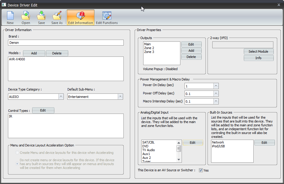
Device Driver Edit: Edit Information
In the Edit Information screen of Device Driver Edit, we have the ability to create/edit some of the basic
information about the device. It is important to be accurate in all fields to ensure proper macro generation.
Each subsection (Driver Information, Driver Properties, Power Management, and Analog/Digital Input & Built-
In Sources) is reviewed in detail.

Driver Information

Brand: Enter the name for the brand in which this device appears in the My Database library. This field prepopulates
when editing a pre-existing driver/codeset. This field is blank when creating a driver from scratch.
Models: Using the Add button, enter the text for the model number of the device for which you are creating
the driver. This Model Number appears when it is searched within My Database. Clicking the Delete button
removes the selected model number from the database.
Device Type Category: Select the category where this device appears in My Database.
Default Submenu: A submenu is the location (on the user interfaces) where this device (and its internal
sources) appear to the end-user. The default submenus that URC Accelerator offers are:
Music
Entertainment
Settings
Info
Lights
Comfort
Security
• AVRs are treated as an exception in the Default Submenu section. The choice made in this drop-down list
reflects where the Internal Sources show up. The AVR device itself always defers to the Settings submenu.
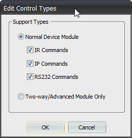
Control Types: This box shows the different command protocols that are currently available for this device.
Clicking the EDIT button allows you to change the protocols available.
• Each command protocol listed in this box has a corresponding tab created in the Edit Functions window. It
needs to be filled with commands from the selected control protocol.
Menu and Device Layout Acceleration Option
• Create Menu and Device layouts for this device when Accelerating
Selecting this option will create a device menu and a device layout along with menus and layouts for any
built-in sources during the Acceleration process.
• Do not create menu or device layouts for this device. If this device has any built-in sources they will still
appear on the menus and layouts will be created for them when Accelerating
Selecting this option will NOT create a device menu or device layout but it WILL create menus and layouts
for all built-in sources during the Acceleration process.
Driver Properties
The Driver Properties section of driver creation operates differently depending upon the type of device chosen
for the driver (General Device vs. AVR/Multi-Zone Device). See below for details.
General Device
When creating a driver and choosing the General Device option, the Outputs window auto-populates with
Main Functions. This is non-editable; however, selecting Edit Zones will open the Edit Zones window where
one can set the port selection (for IP devices) or the serial type (for RS-232 devices).

The Output section of Driver Properties appear differently depending upon the choices made for the driver setup.
Any gear selected, as General (or any generic codeset) populates the Output window with Main Functions.

AVR/Multi-Zone Device
When creating a driver and choosing the AVR/Multi-Zone option, the Outputs window will auto-populate with
Zone 1. If a device has more than one zone, choosing Add will allow additional zones to be named and added.
Likewise, selecting Delete Zone allows zones to be removed (this may be the case if you are using an existing
driver as a template for a new driver). Selecting Edit opens the Edit Zones window where one can set the Port
selection (for IP devices), the Serial Type (for RS-232 devices) and/or Rename any of the zone outputs.

The Output section of Driver Properties will appear differently depending upon the choices made for the
driver setup. Any gear selected, as AVR (or Multi-Zone device) will populate the OUTPUT window with
ZONE 1. This can be edited (see below) to reflect the correct number of zones for this device.
2-Way (VFD)
This section allows the installer to select a specific VFD file from the Edit Modules window. You can also view
the module information from this same section.

Select Module: Clicking on the Select Module button will open the Edit Modules window. This window
shows all the 2-way VFD files. Select the one you would like to use and click OK.

Info: Clicking on the Info button opens the Module Information window. This section shows detailed
information about:
a. Built-in Sources
b. Outputs
c. Version
d. Title
e. Detail

Power Management & Macro Delay
This section allows you to adjust the various action delays for the device. These settings are global (they affect
every command for this device). The delays mentioned below are automatically placed into all macros that
contain Power ON/OFF commands.
Power ON Delay: This is the time (in seconds) that the program waits after issuing a POWER ON command for
this device. This delay allows the device to warm up and prepare to accept the next command.
Power OFF Delay: This is the time (in seconds) that the program waits after issuing a POWER OFF command for
this device. This delay could allow a device to cool down before accepting another command.
Macro Interstep Delay: This is the time (in seconds) that the program waits between each command issued to
the device. Typically, this is set very low (.1 or .2 seconds).
• These settings can cause unnecessary delays during normal system operation. Creating intelligent, variablebased
power commands alleviates this problem.

Example
TV has a 7-second Power ON delay.
AVR has a 4-second Power ON delay.
When the system is first turned ON, these delays are useful and necessary. However, if the end-user returns
to the main menu and selects Watch TV (while the system is already ON), it will take more than 10 seconds for
the user to have access to the controls for Watch TV. (The system will issue a Power ON command to both
devices and wait the required time to move forward). The FIX for this is to use variables to track power status
and then build simple If/Else statements into each of the devices Power Menus. (See the Macro section for
more details.)

Analog/Digital Input
This section allows you to add/name the external inputs for this device.
If you chose to start from scratch, this section will be unpopulated. If
you chose to use an existing driver/codeset as a template, there may be
a pre-populated list showing. Regardless, this list (or lack thereof) will
most likely need to be edited. Selecting the Edit button will open the
Edit Sources window.

Built-In Sources
This section allows you to add all of the internal sources available for this device. These sources are made
automatically available to the end-user and are incorporated into the user interface. If there are sources that
you do not wish the customer to have access to, make sure that they are not included in this list. To
Add/Delete these internal sources select Edit.

Selecting Edit opens the Edit Sources window, which allow for easy Adding or Deleting of internal sources
using the corresponding buttons.

Once this page (Edit Information) is complete and accurate, it’s time to move to the next step Edit Functions.
Select this option from the window ribbon (far right) to get there.

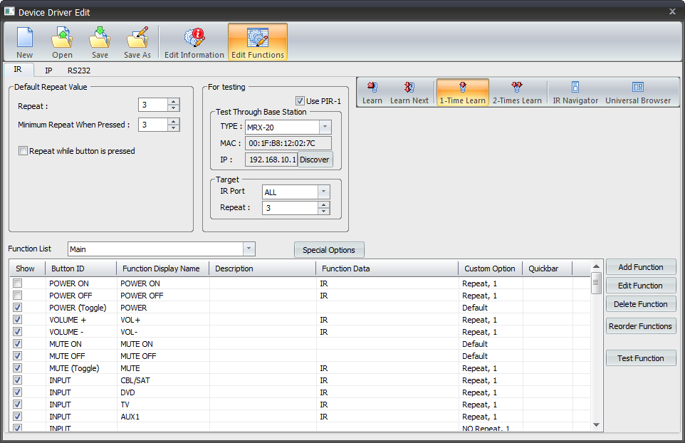
Edit Functions
In this portion of the Driver Creation process, we create/edit all of the information required to control this
device (codeset).
• Codeset: A codeset is a series of commands (IR, IP or RS-232) that control the functions of a device. Every
IR, IP or Serial Device has a codeset that performs this function.
The Edit Functions window is comprised of two main portions: the Settings & Testing section (top half of the
window) and the Function List section (bottom half of the window). Although the Function List section
remains the same (mostly) regardless of the command protocol used (IR, IP or RS-232), these protocols will
have a significant impact on the information required in the Settings & Testing section.
Settings & Testing
Depending upon the control protocol chosen in the Edit Information page of driver creation, you will see one
or more of the following TABS available: IR, IP or RS-232. Each of these tabs has slightly different control
settings, reviewed below.

IR

The Default Repeat Value box has the default repeat settings. The repeat options allow you to either increase
or decrease the number of times each command is sent by each key depress.
The For testing box allows you to set up for testing each command by selecting the base station of your choice
and discovering it for this testing purpose. There is also an option to use the PIR learning device (check that box to use it).
The Target box is to isolate the port used on base station and also allows to change repeats.
The Learn buttons initializes the learn functions if needed codes are not readily available in database.
The IR Navigator allows you to search through the database in order to find your model of your device to test with. The Universal Browser allows you to bring in hex code (in pronto hex format only) and drag the commands directly to the function data rows and columns below.
IP

The Driver Information describes the current settings.
The Default Repeat Value allows repeat increase and decrease as needed. The Ramp Time option is for setting just how fast the volume or channel button ramps changes in either volume or channel surfing per key pressing.
The For testing box allows you to set up for testing each command by selecting the base station of your choice
and discovering it for this testing purpose.
The IP Navigator allows you to search through the database in order to find your model of your device to test with.
RS-232

The Driver Information describes the current settings (which will be present in the device manual you are installing).
The Default Repeat Value allows repeat increase and decrease as needed.
The Ramp Time option is for setting just how fast the volume or channel button ramps changes in either volume or channel surfing per key pressing.
The For testing box allows you to set up for testing each command by selecting the base station of your choice
and discovering it for this testing purpose.
The Serial Navigator allows you to search through the database in order to find your model of your device to test with.
Function List Windowpane
This list contains all of the commands for the device. Regardless of whether the driver was created from
scratch (these fields are blank) or another driver/code set was used as a template (these fields pre-populated)
the same steps apply to completing this driver.

The FUNCTION LIST drop-down menu (upper left) displays different selections based upon the choices made
prior to this window.
General Device: If you chose to create this driver as a General Device the only item in the drop-down menu is
Main Functions. The commands found in this section will be all the commands for the device.
AVR or Multi-Zone Device: If you chose this option in the driver creation process the drop-down menu may
contain the following:
Zone 1 (Main): these are the commands used to control the functions of this device as it pertains to Zone 1
(Main).
Zone X: Each zone contains its own code set as we assume that each of these zones has discrete commands for
control. (i.e. a 3-zone receiver contains at least Zone 1, Zone 2 and Zone 3 in this drop down).

Internal Source 1: Each internal source entered in the Edit Information window appears in this list at least
once. Since URC Accelerator generates a user interface for each of these sources, the codeset for these must
be completed.

Internal Source X (Zone X): If you chose dedicated built-in sources in the Built-In Source Option window,
each of these sources show up multiple times (one for each zone). Remember, by choosing that option you
have told Accelerator that each source has a discrete set of commands per zone.


Special Options: This button allows the user to copy a code set from one page of the Function List window
to another. This is useful when one code set is identical to another as it eliminates the need to re-enter
each code. To use this function, first make sure that you are on the code set page that needs to be filled.
Next, select Special Options and choose copy a function list from the drop-down menu. Once that choice
is made, the next option is to choose the page (from the Function Lists) that you would like to copy from.
A critical point to understand is one of the largest differences between a driver and a generic code set is how
URC Accelerator handles the information.
In traditional programming, each code in the code set is a number. It is the responsibility of the programmer to
place these codes in the right locations, in the proper order, etc., in order to make things happen.
URC Accelerator takes some of the work away by creating the device layouts, creating activity buttons for each
connected internal/external source and developing macros based mostly upon this driver creation process.
Function List (Field Descriptions)
Each field shown in the Function List window is explained below:
Show
This checkbox is used to determine which commands automatically appear in the user interface for
the device/zone/source. This is the first step in creating an intuitive, easy to use interface for the enduser.
Keep in mind, all the commands will always be available (to add to macros, buttons, etc.) in other
steps, this determines the buttons that the end-user sees in the auto-generated user interface.
Button ID
This field is used by URC Accelerator for button mapping and there usually is no reason to change this
field. However, it is still worthy of an explanation. When a codeset is brought in, Accelerator
automatically populates SOME buttons with codes. This is based upon a button ID which is part of the
codeset and allows some level of automation by filling most of the common device functions with the
appropriate codes. As you will notice, this process is virtually flawless, which is why very little
modification will occur in this column. For a detailed explanation of Button IDs and how they operate
in URC Accelerator see the Appendix: Button IDs.
Function Display Name
This is the text that appears on any soft button that needs to be created (if one of these buttons is
necessary). The creation of these soft buttons is determined by the interface the device is populating.
The PLAY button is a perfect example:
•On a TRC-780, the hard button pre-labeled PLAY is automatically populated with this command.
•On a TKP-2000, where there is no hard play button, a soft button will be created and labeled PLAY
(based on the text in the Function Display Name field).
Description
This is only for internal use and note-taking; it has NO affect on operation or the generated user
interface.
Function Data
This field shows the codeset data for the device. If this field is empty, there is no data for the
command. The field, once a code is entered, shows either IR (if it is an infrared code) or a string of
characters (if it is an RS-232 or IP code). Filling these commands with codes are covered in the Using
The Function List section.
Custom Option
This field shows any code customization set for that command. Default means that it will use the
preferences defined in the Settings & Testing portion of this step, however, these settings can, if
necessary, be adjusted per command by using the Edit Function button (see the Using The Function
List section).
Using The Function List
Populating each function list with accurate codes is paramount to making sure that the correct macros,
sources and inputs are defined in Accelerator and to the end-user. For those familiar with URC’s CCP Program,
there are some similarities. Those unfamiliar should still easily understand this step.
Step 1: Populate Codes
a. If the codes are already in place (you used another driver/code set as a template) skip to Step #2.
b. Assuming the Function List has no commands (data) entered, the
first step is to find the code set in the URC Database that matches
the device/zone/source.
In the Setting & Testing section of this window, open the IR
Database Navigator to have access to the URC Database.
Browse to the device that has the correct codes. If there is no
available codeset, you must learn each command using the
learn function in the Settings & Testing section of this window.
c. Once the correct device has been found, you can DRAG codes
from the IR Database Navigator window to the correct line in the
Function List window. Or click on Save All, which automatically
saves all of the associated buttons (based on Button ID) to the
correct command location. It is important to verify this
automated process by looking at the commands in the window
and ensuring that there are associated codes.

Step 2: Redefine External Inputs
a. In order for URC Accelerator to automate the process of input selection, we must define the inputs.
b. When a codeset is associated with a device the inputs are codes and are not associated, by
Accelerator, as INPUT codes. Redefining the existing codes that are associated with inputs to INPUT
codes is a simple process.
c. You will notice that each of the External Inputs, entered in the External Input section of the Edit
Information window, appear at the bottom of the function list with input in the Button ID field. By
default, these External Input commands will not have an associated codeset, although their generic
code counterparts will.
Using an AVR as an example, when importing a codeset (using save all) a command with an
associated codeset appears for the device’s inputs (HDMI 1, HDMI 2, etc.).
These codes, although accurate, are not associated with input command. In order for Accelerator
to be able to use this information to create macros and interfaces you must make this association.
To make the association, find the newly created input commands and drag (using the appropriate
navigator) the corresponding input command to that field.
Step 3: Add Functions
a. If all of the functions needed are not, by default, created in the driver creation process, adding a
new command (with an associated control code) is easy.
b. The add function button (to the right of the Function List window) adds a new, unnamed, command
to the bottom of the function list. This is an empty command that will need to be named (in the
Function Display Name field) and filled with the correct code (using the appropriate navigator IR,
RS-232 or IP).
Step 4: Edit Functions
a. The Edit Function button allows you to edit the setting of a specific command in the Function List
window.
b. By default, each command/code operates based upon the global settings made in the Settings &
Testing section of this window. However, if a specific command requires special adjustments of
these defaults, selecting the command and clicking the edit function will allow you to change how
that command works.

Step 5: Delete Functions
a. If there are unnecessary commands within the Function List, selecting the command, followed by
clicking the delete function button removes it from the list.
Any command removed using this method is no longer be available to add to any button/macro in
other programming steps.
If you wish to have the ability to see a command in other programming steps, but do not want it to
appear on the user interfaces for this device, uncheck the box in the show field for that command.
Step 6: Reorder Functions
a. This operation allows you to define the device
layout for all projects where this device in
used. Only commands that have show enabled
(check box is checked) will appear in the
device layout section.
b. The reorder window appears with all of the
enabled (show box checked) commands
available that do not have a hard button
assigned. By default, buttons are created for all
commands in the order they are placed within
the functions list window. Use this window to
change the order that the buttons will appear
on the different pages.
Use the TRC-780 button layout as a reference for the
example list below. If this were PAGE 1, button #6 would
contain Video 1 VCR/DVR.
Step 7: Test Functions
a. Use this function to individually test any of the codes
entered for the functions in this window.
Step 8: Repeat
a. The same steps (#1 - #7) should be repeated for each
item listed in the Function List drop-down menu.
b. Although some devices are a repeat of the functions
found in main functions (general device) or Zone 1
(AVR) and could easily be duplicated by:
Use the appropriate navigator and use the save all
command. This works well for devices that did not
need much editing
Use the special function feature to copy a page (that
has already been edited) to another (that has not).

as