URC HDA devices and software provide countless options to configure and optimize audio settings to achieve performance and flexibility for almost any application.
One of those features is the flexibility of the HDA-1600 amplifier and the microphone inputs.
This article provides a better understanding when configuring the microphone inputs on the HDA-1600 and details the procedure for configuring the microphone input settings when using Accelerator 3 or TC Flex 2 software.
When using microphones in an HDA system, it is important to set them up properly, using Accelerator or TC Flex 2 software. All the tools you need to calibrate your microphones are available and can be set live using URC software.
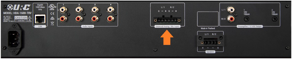
HDA-1600 rear panel microphone connections (see image below):
Configuration Steps:
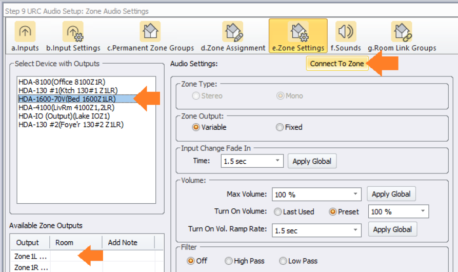
- After connecting the microphone to the HDA-1600 chassis, open Accelerator or TC-Flex 2.0 software. Go to Step 9e in Accelerator, Step 7e in TC-Flex 2.0, click on the HDA-1600 amplifier.
- Click on the zone that is using the microphone to set it up.
- Select “Connect To Zone” (as shown in the image below).
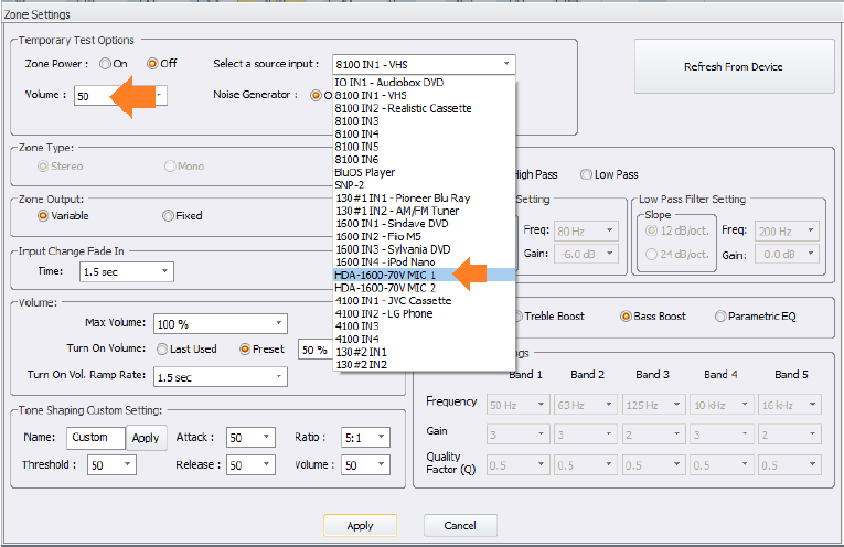
4. In the “Connect To Zone” window, Power the zone “ON”.
5. Set a usable volume level.
6. Select the microphone in the zone (as shown in the image below).
7. Next, go to Step 9b in Accelerator (Step 7b in TC-Flex 2.0). Select the HDA-1600 amplifier.
8. Select the “Connect and Set Live” option for the microphone that is being setup (as shown in the image below).
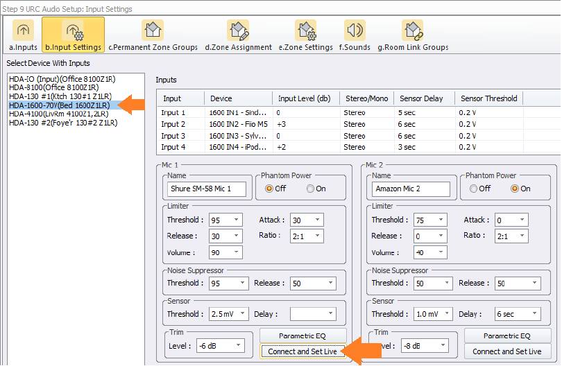
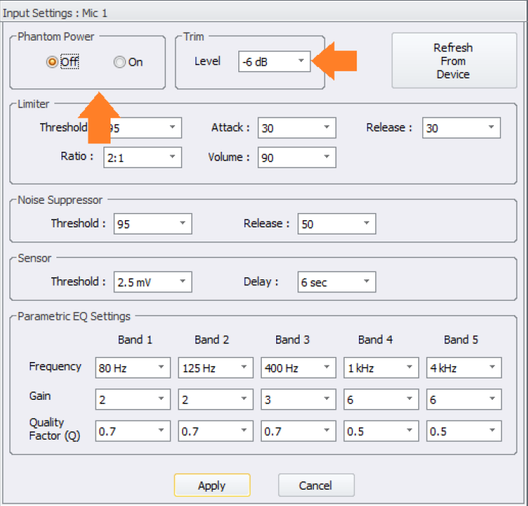
9. Set Phantom Power to “ON” or “OFF”, based on the microphone you are using (see image below).
10. Set the “Trim” value. This is the input level of your microphone.
a. Microphones that use Phantom Power tend to have a higher audio output, so the “Trim” value will be lower for these microphones.
b. Microphones that are passive, that do not use Phantom Power, tend to require a higher “Trim” value.
11. View the front panel of your HDA-1600 – If you see the “Clipping” LED for your microphone, adjust the “Trim” value up for your microphone until the “Clipping” LED momentarily lights up red while you are talking loudly into your microphone.
12. When the “Trim” value is set correctly, the “Clipping” LED will barely illuminate when you are speaking as loud as possible into the microphone or tapping the microphone.
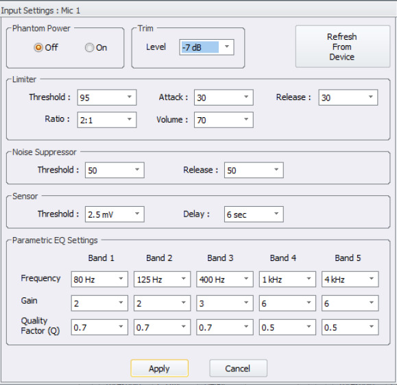
13. Example settings for a non-Phantom Power microphone, Shure-SM58 (see image below):
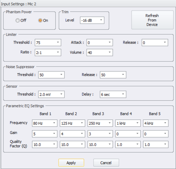
14. Example settings for a Phantom Power microphone, Neewer NW-700 (see image below):
15. Limiter: A Limiter’s main function is to bring up the audio level of the microphone without allowing the peaks to cause the signal to clip.
Limiter Parameters
Threshold
Limiters will have an adjustable threshold level, which is also often referred to as the “ceiling”.
This sets the signal level at which the Limiter begins compressing the microphone’s audio. Compression does not occur until the signal level reaches the threshold, and compression will cease once the incoming signal level drops below the threshold.
Ratio
Your ratio control lets you decide how much compression is applied once the microphone signal crosses that threshold — the actual ratio being referred to is the input level compared with the output level. At a ratio of 2:1, for example, every 2dB of signal level over the threshold will be compressed to deliver only 1dB of signal level increase at the output stage.
Attack
The attack control on a Limiter determines how long it takes for the compressor circuit to reach (nearly) full compression — these are often very short values timewise, sometimes down into the microsecond range. A good way to look at the attack control is that it determines how much of a sound’s initial attack will be compressed — longer attack times allow more of the initial attack to slip through before compression begins.
HDA Limiter Attack times are minimum 5 ms, maximum 100 ms.
if Attack Time in Accelerator is set to =< 5, actual attack time = 5ms
if Attack Time in Accelerator is set to = 6, actual attack time = 6ms
if Attack Time in Accelerator is set to = 7, actual attack time = 7ms
if Attack Time in Accelerator is set to = 8, actual attack time = 8ms
if Attack Time in Accelerator is set to = 9, actual attack time = 9ms
if Attack Time in Accelerator is set to = 10, actual attack time = 10ms
...and so on
if Attack Time in Accelerator is set to = 100, actual attack time = 100ms
Release
Like attack, the release control determines how long it takes compression to stop once the incoming microphone signal level falls below the threshold. Setting this control too short can cause the compressor to “pump” or “breathe” — setting the release too long can cause equally unnatural sound effects.
HDA Limiter Release times are minimum 25ms and goes to 5 seconds.
if Release Time in Accelerator is set to = 0, actual release time = 25ms
if Release Time in Accelerator is set to = 1, actual release time = 50ms
if Release Time in Accelerator is set to = 2, actual release time = 100ms
if Release Time in Accelerator is set to = 3, actual release time = 150ms
if Release Time in Accelerator is set to = 4, actual release time = 200ms
if Release Time in Accelerator is set to = 5, actual release time = 250ms
if Release Time in Accelerator is set to = 6, actual release time = 300ms
if Release Time in Accelerator is set to = 7, actual release time = 350ms
if Release Time in Accelerator is set to = 8, actual release time = 400ms
if Release Time in Accelerator is set to = 9, actual release time = 450ms
if Release Time in Accelerator is set to = 10, actual release time = 500ms
...and so on
if Release Time in Accelerator is set to = 100, release time = 5000ms
Level (Makeup Gain)
Because Limiter compression essentially lowers the volume of your microphone audio in a dynamic, intelligent way, you may need to apply some makeup gain to bring the signal level back up after compression occurs. Use the output level or gain control on your compressor in conjunction with its bypass button to quickly compare and match the level of your compressed audio to the incoming signal.
So Where Do I Start?
You could start with the example settings for a Phantom Powered Microphone and a non-Phantom Powered Microphone listed earlier in this document. Or you can tune the limiter yourself. Regardless of what type of audio signal you are applying a Limiter to, it will be helpful to have a go-to starting point with any Limiter. With the controls set as explained below, you will be in a good position to tackle setting up a microphone’s Limiter.
Threshold
Start with this turned all the way up (set to 100 in Accelerator). By doing this, you’ll be able to gradually introduce compression by lowering the threshold, which will better help you hear the effect it’s having on your audio.
When testing a Limiter with a Microphone, use the "Connect and Set live" option in Accelerator, Step 9b for an HDA-1600.
When testing the preset "Tone Shaping" limiters for a zone, along with setting the "Custom" Tone Shaping Limiter for a zone, use the "Connect To Zone" option in Accelerator, Step 9e.
Attack/Release
There is a lot of nuance in these controls; a good place to start would be "50" for both of them.
Ratio
Start with a moderate setting of 2:1. You can always increase or decrease this after you have gotten the threshold and attack/release controls dialed in.
Level (Makeup Gain)
Start with this at "0" (no boost or cut). Increase this setting as desired to increase the audio output level for the selected source at the zone's speakers.
HDA Uses "Soft Knee" Compression
A soft knee setting applies the compression gradually until the full ratio is reached. This makes the transition from uncompressed to compressed audio smoother and less abrupt. Also, soft knee settings do not wait until the threshold has been crossed to apply compression. Instead, the compressor gradually applies compression to the audio signal as it approaches the threshold and does not reach the full ratio amount until somewhere past the threshold.
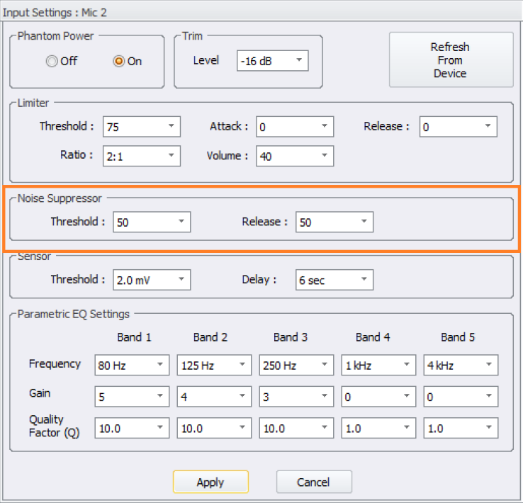
16. Noise Suppressor: A Noise Suppressor is essentially a system that softly mutes the microphone when it is not in use. This helps with eliminating background noise and feedback when the microphone is not being spoken into.
a. Threshold: The THRESHOLD control sets how sensitive you wish the Noise Suppressor to be, i.e. the “threshold” at which the Noise Suppression begins to do its work. Setting the THRESHOLD to "0" will cut nearly everything, including loud signals. A Threshold setting of “100” will result in the Noise Suppressor essentially not cutting any signals at all.
b. Release: The release control is used to define the length of time the Noise Suppressor takes to change from open to fully closed. It is the fade-out duration. A fast release abruptly cuts off the sound, whereas a slower release smoothly attenuates the signal from open to closed, resulting in a slow fade-out.
c. A good place to start is to set both the Threshold and the Release times to “50” and adjust them from that point.
17. Sensor: These settings are used to affect logic in macros by providing the ability to trigger a logic event by audio being present or being ended into a microphone. Typically, the default settings will work fine for most applications. If you are experiencing “false” triggers you may want to adjust the Threshold and Delay settings. Each microphone setup is unique.
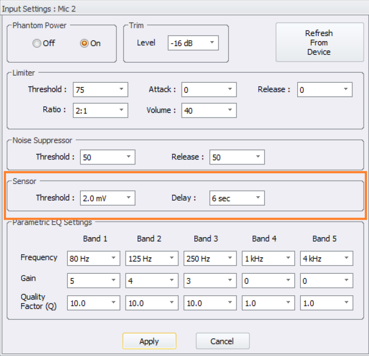
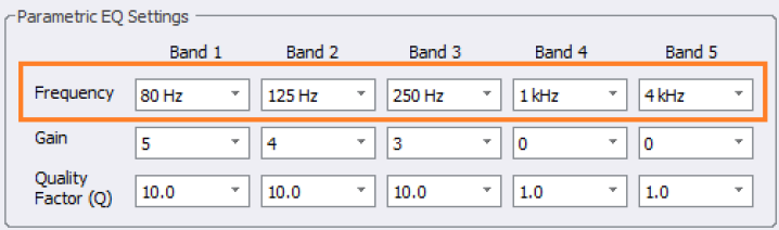
18. The Microphone’s Parametric EQ:
A high-quality parametric EQ is one of the most important tools when “tuning” the sound of microphone. Each microphone input has its own dedicated Parametric EQ. The Microphone’s Parametric EQ is designed to provide greater and more accurate control over tone and frequency – a significant leap beyond just simple bass and treble tone controls. They can raise (boost) and lower (cut) the decibel output of specific bands (frequencies of sound).
Setting up the Microphone’s Parametric EQ
Frequency Value
Each band allows you to set the band’s frequency position by clicking and an selecting the frequency value.
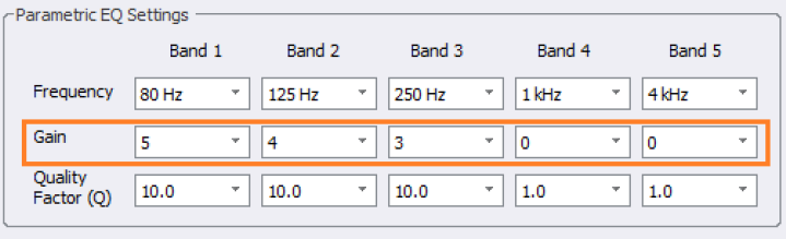
Gain Value
The middle row allows you to set the gain value of the band, which is by how much you boost or cut the selected frequency of the band. Gain values range from -20dB to 6dB.
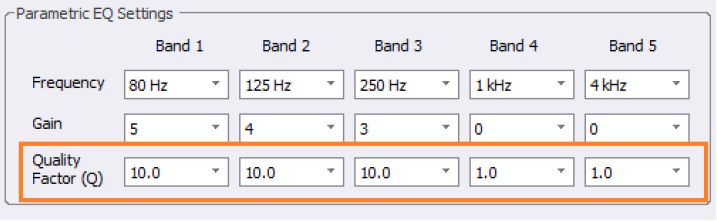
Q Value
The bottom row is the Q value and controls the width of the band or simply put how many frequencies will be affected by the band. A high Q value will give you a wide band and affect more frequencies. A low Q value will give you a narrower band and is great to cut or boost more specific frequencies.
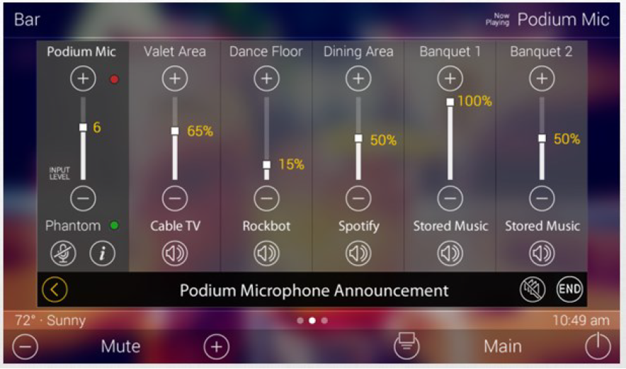
19. The Microphone User Interfaces:
a. Residential
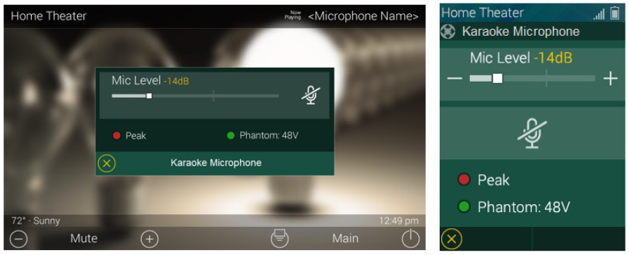
b. Commercial
Additional Information & Resources:
To learn more about HDA products and programming, please see the HDA Programmers Guide, the HDA Modules Users Guide, or the Accelerator 3 online Programming Guide.