URC HDA devices and software provide countless options to configure and optimize audio settings to achieve performance and flexibility for almost any application.
The following article helps you understand the HDA-130 chassis heat during normal amplifier operation.
The HDA-130 Amplifier uses an amplifier IC (integrated circuit) that requires cooling (dissipation of heat generated by the component). The process of dissipating heat generated by an electronic component is commonly referred to as a “Heat Sink”.
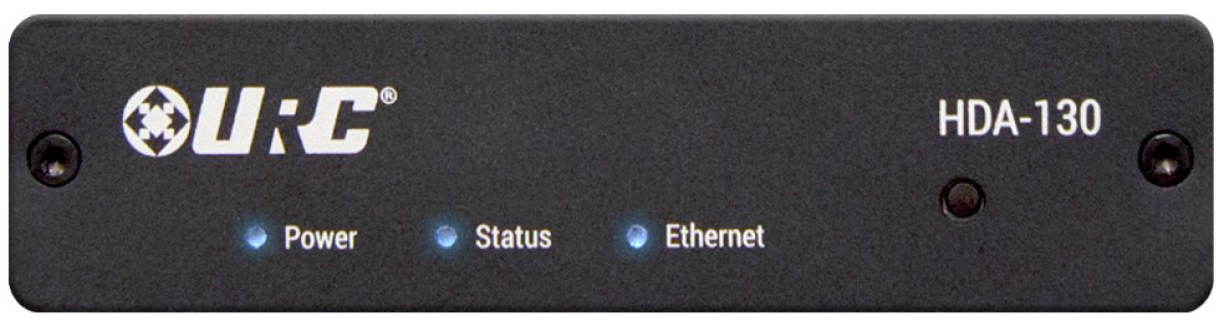
HDA-130 front panel (see image below):
Understanding the HDA-130 chassis heat
- Because of the small chassis size, it is not practical to mount a legacy-style heat sinking tower on the IC.
- Knowing this, the IC lays flat against the amplifier chassis. The IC uses the amplifier chassis to dissipate the heat it generates. The IC uses the amplifier chassis as its “heat sink”. This is normal practice for many electronic devices, including mobile phones.
- The HDA-130 amplifier feels warm to the touch under a normal load. This is expected and means the amplifier is operating correctly.
- When using an HDA-130 in a rack, mounted on a rack tray, you should attach the provided rubber feet to the bottom of the chassis. This ensures proper airflow convection from the bottom of the chassis to the top, to cool the HDA-130 amplifier. An installer shouldn't just lay the HDA-130 amplifier on the rack tray without the rubber feet because this blocks the air inlets at the bottom of the amplifier chassis.
Additional Information & Resources:
A good video tutorial describing the design and function of a heat sink can be found here.
For more information on “Heat Sinks” and how they work, click here.
To learn more about HDA products and programming, please see the HDA Programmers Guide or the Accelerator 3 online Programming Guide.